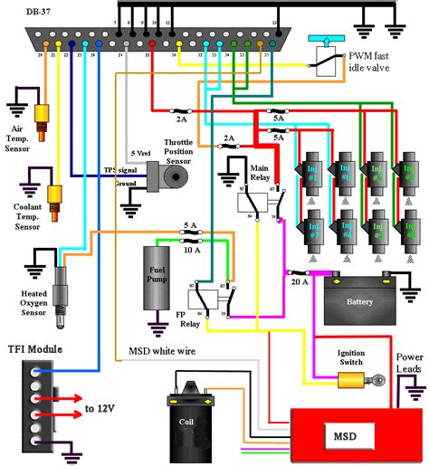
Fuel injector wiring diagram 5af6d48624db3.gif
24/04/2024 13:18 - Cnoeuznl -

94 & 95 Mustang Electrical and Vacuum diagrams. Mustang Cylinder Head, Basic Mods, Engine Mechanical Information. Mustang EEC IV 5.0 HO Information. Note: Some of this may be A9L Specific! Mustang Automatic and Manual Transmission Information. Mustang Electrical and Vacuum diagrams.accurate wiring diagram and use your ohmmeter to verify that you are on the correct wire from the DME to the injector. Now that you have identified the correct wire, connect the injector side of the wiring harness to battery negative. Then, at the DME side, connect a test light (the load) to the injector terminal to be tested, then connect it toFeb 28, 2022 · The injector fuse should be fuse 57 (25 amp - marked with a red box on the photo below) in the left rear engine compartment. It wouldn't hurt to do a quick check on all of the fuses, though. I'll be curious to hear what the resistance check on the injector reveals. Thanks, Wendy. Image (Click to make bigger) Was this. Share. Access our free Wiring Diagrams Repair Guide for GM S-Series Pick-ups and SUV's 1994-1999 through AutoZone Rewards. These diagrams include: Fig. 1: Index of Wiring Diagrams. Fig. 2: Sample Diagram: How to read and interpret wiring. Fig. 3: Wiring Diagrams Symbols. Fig. 4: 1996 GM 2.2L Engine Schematic. Fig. 5: 1997 GM 2.2L Engine Schematic.4045 (4.5L and 6.8L Level 11 Electronic Fuel System with Denso HPCR) 4045 (6.8L - Level 4 Electronic Fuel System with Bosch VP44 Injection Pump) 4045 (Level 34) 4045 (PowerTech Final Tier 4-Stage IV) 4045 (PowerTech Interim Tier4-Stage III B 6068 (PowerTech Interim Tier 4-Stage III B (174hp) 6090 PowerTech (Final Tier IV – Stage IV)Black-Orange is injector power, as you already found out. The other wire is the 'negative' pulse that actually fires the injector. Since they are paralleled (I think the 4-cylinder is also run in pairs - though the diagrams show them spliced together, which may or may not be true), the other side should read basically the same DC voltage whenever the injector isn't firing (which is most of the ...not much of a diagram but best I can do. Injector 1: pin 45 and pin 53. Injector 2: pin 54 and pin 51. Injector 3: pin 55 and pin 52. Injector 4: pin 56 and pin 58. Injector 5: pin 46 and pin 60. Injector 6: pin 57 and pin 59. First pin # is out put voltage or signal wire Second pin #is ground or return. Hope that helps.These GM wiring diagrams provide schematics for vehicle model years 1988 through 1998. Fig. 1: Index of Wiring Diagrams. Fig. 2: Sample Diagram: How to Read and Interpret Wiring Diagrams. Fig. 3: Wiring Diagram Symbols. Fig. 4: 1988-98 GM-C/K Series Wiring Schematic. Fig. 5: 1988-98 GM-C/K Series Wiring Schematic.Mike Schneider. Expert. 245 Answers. I wold look around the top engine .by are filter.or follow your cranking weir from starter bakwords maybe to relay look for chafing.what Sta's hot Will cranking coil distributor.or unplug one injector at a time and try this wold be my last try. try using breaker not heavy jumper weir have sum one tap the key ...When using the Haltech long flying lead harness this is already pre-terminated, injector power is supplied via a fused and relay switched circuit. If you are wiring your own harness you will need to ensure that injector power is fed into the ECU via the injector power pins. Failing to do this may result in unstable operation and electrical noise.Refer to Ford Wiring Diagrams for Wiring 89 D IAGN O STIC CO D ES O - Self Test - Key On Engine Off R - Key On Engine Running C - Continuous Operation REGEN - Test Follows a REGEN CYCLE SHUT DOWN - Test Follows Key Off KO - Test Operates at Key On 1PC - Once Per CycleFuel Pump Wiring Diagram Help Jeep Enthusiast Forums. 2006 Jeep Grand Cherokee Fuel Pump Doesn T Power Up. Fuel Injector Circuit Wiring Diagram 1993 1995 4 0l Jeep Cherokee. Ignition System Wiring Diagram 1997 1998 4 0l Jeep Cherokee. Fuel Pump Electric 1984 1991 Jeep Cherokee Xj Online Manual. 98 Xj No Power To Fuel Pump Jeep Cherokee Forum ...Fuel Pump Wiring Diagram Help Jeep Enthusiast Forums. 2006 Jeep Grand Cherokee Fuel Pump Doesn T Power Up. Fuel Injector Circuit Wiring Diagram 1993 1995 4 0l Jeep Cherokee. Ignition System Wiring Diagram 1997 1998 4 0l Jeep Cherokee. Fuel Pump Electric 1984 1991 Jeep Cherokee Xj Online Manual. 98 Xj No Power To Fuel Pump Jeep Cherokee Forum ...Black-Orange is injector power, as you already found out. The other wire is the 'negative' pulse that actually fires the injector. Since they are paralleled (I think the 4-cylinder is also run in pairs - though the diagrams show them spliced together, which may or may not be true), the other side should read basically the same DC voltage whenever the injector isn't firing (which is most of the ...If it helps, here's a description of the 1999 fuel injector wiring: Each injector connector will have two wires, one of the wires will be 12 VDC power from the Automatic Shut Down (ASD) relay (when the engine is running). The 12 VDC wires are all the same color - Dark Green/Orange tracer. Each injector connector will have an individual driver ...To drive the fuel injector, the FICM produces two control signals for each injector. The open coil is driven (via a 20A pulse) to open the injector. This shifts the spool valve in the injector to the open state. Once this has taken place, high pressure oil is directed on top of the injector intensifier piston. In result, fuelFuel Injector Circuit Wiring Diagram (1999-2002 V8 Chevrolet Silverado, GMC Sierra) NOTE: The above fuel injector circuit wiring diagram applies to the following vehicles: 4.8L Chevrolet Silverado (1500, 2500): 1999, 2000, 2001, 2002.My main question is about the second wire on the injectors. Do they all connect go the 30 from the fuel pump relay? In the harness wiring diagram it shows the 30 terminal from the relay going to the J & K terminals on the injector main harness. Does 3 go to J and 3 go to K being it's a 4.3L V6?Injector Wiring Diagram. 887 Views 2 Replies 2 Participants Last post by Monty65 , Jan 23, 2023 Jump to Latest. Monty65 Discussion starter · Jan 23, 2023. Does anyone have the wiring diagram they could post for the fuel injector harness on a 2015 Town and Country, 3.6L engine? Thanks. Reply.Re: Fuel injector wiring. the fuel injectors are mixed up need the wire color for all the injectors pigtail going to the injectors. The injectors are glorified solenoids and the polarity doesn't really matter, the different-colored wires on the ECM side just need to go to the correct cylinders.Part 2 of 2: Testing injector wiring. Step 1: Turn the car on. Turn the key to the second (ON) position for this test. You want battery power flowing, but don’t want the engine running. Step 2: Set up DVOM to measure DC voltage. Use the lowest range possible if the meter doesn’t auto range. The block diagram of the Fuel Injection System is as shown in the Fig. 3. The time constraints of the system are imposed by the characteristics of the internal combustion engine to be controlled. It is defined that a turn of the engine i.e. 360° is completed once in every 5 micro seconds for 12,000 rpm.SOURCE: 87 toyota pickup 4x4 22ret i have no injector OK, the computer grounds one of the curciuts on each injector to pulse it. Interesting information from alldata, the autodata and mitchell and Bosch AFC all show a code 11 as being ECM (B+) that I have, which could be the EFI main relay, fuse, fuse link or wiring (usually one of the wires on the battery terminal have broken off or corroded ...Please check out the diagrams (below). There are three pages, each split into two images for better resolution (example page 1A and page 1B). Here's a repair guide containing OBD II trouble code definitions: https://www.2carpros.com/trouble_codes/obd2.Tips on selecting the proper type of fuel injector connector. Fuel injector connectors are susceptible to deterioration due to aging, and wear and tear. A fuel injectors location on the engine exposes them to intense heat, vibration, and chemical fumes. Over time, these will cause the connectors’ nylon body to deteriorate and eventually break.Wiring Code Identification Information . WIRE CODE IDENTIFICATION . Each wire shown in the diagrams contains a code (Fig. 1) which identifies the main circuit, part of the main circuit, gauge of wire, and color. The color is shown as a two-letter code, which can be identified by referring to the Wire Color Code Chart (Fig. 2).My main question is about the second wire on the injectors. Do they all connect go the 30 from the fuel pump relay? In the harness wiring diagram it shows the 30 terminal from the relay going to the J & K terminals on the injector main harness. Does 3 go to J and 3 go to K being it's a 4.3L V6?2004 Mazda Rx8 Fuel Injector Connector Diagram Rx8club Com. Rewiring The Rx 8 Fog Lights. Rx8 Wiring Manual Rx8club Com. Power Seats Mazda Rx 8 2004 System Wiring Diagrams 자동차 배선도. All Wiring Diagrams For Mazda Rx 8 R3 2009 Cars. I Have A 2004 Mazda Rx8 Took It To Body Get Some Minor Paint Work And Detailing Done When Got BackIf it helps, here's a description of the 1999 fuel injector wiring: Each injector connector will have two wires, one of the wires will be 12 VDC power from the Automatic Shut Down (ASD) relay (when the engine is running). The 12 VDC wires are all the same color - Dark Green/Orange tracer. Each injector connector will have an individual driver ...Conclusion. Zafira wiring diagrams are an important tool for technicians when diagnosing vehicle issues. With these diagrams, technicians can easily identify components, power output, and trace circuits. This can lead to quicker and more effective repairs. Understanding how to read and use these diagrams is essential for any technician looking ...Mike Schneider. Expert. 245 Answers. I wold look around the top engine .by are filter.or follow your cranking weir from starter bakwords maybe to relay look for chafing.what Sta's hot Will cranking coil distributor.or unplug one injector at a time and try this wold be my last try. try using breaker not heavy jumper weir have sum one tap the key ...1. Fuel Tank 2. Fuel Supply from Tank 3. Pre-filter 4. Hand Primer 5. Low Pressure Fuel Pump 6. Fuel Bypass Valve 7. Water Coalescer / Final Filter 8. High Pressure Fuel Pump 9. Fuel Rail 10. High Pressure Fuel Injector Lines 11. Fuel Injectors 12. Needle Return Line 13. Needle Return Pressure Control Valve 14. Fuel Accumulator 15. Fuel Return ...Video explains the how to test the Fuel Injector Electrical Actuation Diagnostics using a Wiring Diagram. See how to go about it.https://www.paypal.com/donat...Injector Wiring Diagram. 887 Views 2 Replies 2 Participants Last post by Monty65 , Jan 23, 2023 Jump to Latest. Monty65 Discussion starter · Jan 23, 2023. Does anyone have the wiring diagram they could post for the fuel injector harness on a 2015 Town and Country, 3.6L engine? Thanks. Reply.Fig. 11: Comanche Multi-Point Fuel Injection Wiring Diagram (Wiring Diagram Not Available for Cherokee & Wagoneer Models) ’ DO NOT UNFASTEN THE SENSOR WIRE HARNESS CONNECTOR. INSERT THE VOLTMETER TEST LEADS THROUGH THE BACK OF THE WIRE HARNESS CONNECTOR TO MAKE CONTACT WITH THE SENSOR TERMINALS. FUEL INJECTOR TEST PROCEDURE CHARTFuel injectors are mechanical devices used to inject/spray fuel into engines to produce the correct air-fuel mixture, leading to efficient combustion. In 1920, Bosch created the first diesel fuel injector in response to rising fuel demand and prices. Introducing fuel injection to vehicles improved acceleration and fuel efficiency, making ...1. Fuel Tank 2. Fuel Supply from Tank 3. Pre-filter 4. Hand Primer 5. Low Pressure Fuel Pump 6. Fuel Bypass Valve 7. Water Coalescer / Final Filter 8. High Pressure Fuel Pump 9. Fuel Rail 10. High Pressure Fuel Injector Lines 11. Fuel Injectors 12. Needle Return Line 13. Needle Return Pressure Control Valve 14. Fuel Accumulator 15. Fuel Return ...My main question is about the second wire on the injectors. Do they all connect go the 30 from the fuel pump relay? In the harness wiring diagram it shows the 30 terminal from the relay going to the J & K terminals on the injector main harness. Does 3 go to J and 3 go to K being it's a 4.3L V6?Video explains the how to test the Fuel Injector Electrical Actuation Diagnostics using a Wiring Diagram. See how to go about it.https://www.paypal.com/donat...OEM GM parts are the best for restoring your vehicle to factory condition performance. This part fits specific Chevrolet Cobalt, HHR, Malibu models. It fits Pontiac G5, G6, Solstice. It also fits Saturn Aura, Ion, Vue. Affordable, reliable and built to last, GM part # 12604950 Harness Assembly, Fuel Injector Wiring stands out as the smart option.Fig. 11: Comanche Multi-Point Fuel Injection Wiring Diagram (Wiring Diagram Not Available for Cherokee & Wagoneer Models) ’ DO NOT UNFASTEN THE SENSOR WIRE HARNESS CONNECTOR. INSERT THE VOLTMETER TEST LEADS THROUGH THE BACK OF THE WIRE HARNESS CONNECTOR TO MAKE CONTACT WITH THE SENSOR TERMINALS. FUEL INJECTOR TEST PROCEDURE CHARTRefer to Ford Wiring Diagrams for Wiring 89 D IAGN O STIC CO D ES O - Self Test - Key On Engine Off R - Key On Engine Running C - Continuous Operation REGEN - Test Follows a REGEN CYCLE SHUT DOWN - Test Follows Key Off KO - Test Operates at Key On 1PC - Once Per CycleIf fault follows the fuel injector(s) swap: Replace the affected fuel injector(s) only. If the fault remains on the original cylinder: Perform a temporary overlay from the ECM to the fuel injector and retest. If the fault no longer returns after an extended test drive: Replace the engine wiring harness and the 8 pin injector harness. Tips on selecting the proper type of fuel injector connector. Fuel injector connectors are susceptible to deterioration due to aging, and wear and tear. A fuel injectors location on the engine exposes them to intense heat, vibration, and chemical fumes. Over time, these will cause the connectors’ nylon body to deteriorate and eventually break.the fuel rail. A return line from the fuel rail takes excess, or bypass, fuel back to the vehicle tank. Your fuel pump should be mounted under the floor near the fuel tank, or inside the fuel tank. Connected to the harness power feed, the fuel pump will operate for 2 seconds when the ignition is turned on. It willRemove the air cleaner assembly. 3. Remove the wiring harness connectors and the brackets and move aside. 4. Remove the throttle cable and the bracket from the upper intake manifold. 5. Remove the cruise control cable, (if equipped). 6. Remove the fuel lines from the intake to the rear of the block.the fuel rail. A return line from the fuel rail takes excess, or bypass, fuel back to the vehicle tank. Your fuel pump should be mounted under the floor near the fuel tank, or inside the fuel tank. Connected to the harness power feed, the fuel pump will operate for 2 seconds when the ignition is turned on. It willSOURCE: 2000 ranger fuse diagram. Fuel Pump relay switch is in the main box usually located on the drivers side Fender in a black box. According to the owner's manual in the power distribution box in the engine. compartment (Ford recommends disconnecting your battery) Relay # 5 is the fuel pump relay , and also in the PD BOX is a 20 amp mini-fuse.The wiring in the diagram doesn't match-up with the wires in my system, or it doesn't seem to. I put the yellow-wired plug in the #4 injector and the tan-wired plug in the #3 injector, and I'm pretty sure those two are good, but the first two don't match-up in color at all... but I also don't know what LG and LB means.The fuel injector wiring diagram will show the connections between the fuel injector, the engine control unit (ECU), and the power supply. The power supply is typically a battery or an alternator. The ECU is responsible for controlling the fuel injector, and it will receive signals from the sensors in the engine.Mustang Wiring, Fuel Injection, and EEC Information, Use the information at your own risk. There is no claim to accuracy.Isuzu Trooper 1995-2001 Electrical Wiring Manual. Isuzu Axiom 2002 Electrical Wiring Diagrams. Isuzu Axiom 2003 Electrical Wiring Diagrams. Isuzu Ascender 2003 Electrical Wiring Diagrams. Isuzu Ascender 2004 Electrical Wiring Diagrams. Isuzu VehiCross 1999 Electrical Wiring Diagrams.Injector Wiring Diagram. 887 Views 2 Replies 2 Participants Last post by Monty65 , Jan 23, 2023 Jump to Latest. Monty65 Discussion starter · Jan 23, 2023. Does anyone have the wiring diagram they could post for the fuel injector harness on a 2015 Town and Country, 3.6L engine? Thanks. Reply.1. Mechanically Controlled Fuel Injectors. They are the fuel injectors in which the control of the fuel speed , quantity, timing and pressure is done mechanically with the help of spring and plunger which takes the input from the cam and fuel pump arrangement or by fuel distributor (advanced one). 2. Electronically Controlled Fuel Injectors.Other than the fuel pump and engine control unit (ECU) having been replaced by the owner, the 280Z was in complete and original condition. It also had two extra ECUs lying in the back seat that had been used for “testing.”. This 1976 Datsun 280Z is equipped with a 2731cc SOHC engine, Bosch L-Jetronic fuel injection and four-speed manual ...The block diagram of the Fuel Injection System is as shown in the Fig. 3. The time constraints of the system are imposed by the characteristics of the internal combustion engine to be controlled. It is defined that a turn of the engine i.e. 360° is completed once in every 5 micro seconds for 12,000 rpm.The fuel pump wiring was a bit different from the other power relays. In the original DeLorean wiring, fuse 7 was used for the Lambda system, frequency valve, CPR and fuel pump. Save for the fuel pump, none of those components were in the car anymore, so I decided to simplify things by reusing fuse 7 for the fuel pump and LC-2, replacing the ...accurate wiring diagram and use your ohmmeter to verify that you are on the correct wire from the DME to the injector. Now that you have identified the correct wire, connect the injector side of the wiring harness to battery negative. Then, at the DME side, connect a test light (the load) to the injector terminal to be tested, then connect it toTo be nice - and since I already had the process worked out - I went ahead and did it for all of the Coffee Table Book wiring diagrams of which I am aware. They are: Wiring Diagram - 2003 Powerstroke 6L - Single Alt - Full.pdf. Wiring Diagram - 2003 Powerstroke 6L - Dual Alt - Full.pdf. Wiring Diagram - 2004 Powerstroke 6L - F-Series - Single ...A common problem with the 7.3 are the valve cover gaskets which contain the wiring harness for both the injectors and the glow plugs, so that is the first suspect. I would recommend replacing the gaskets as a first step however I have attached all the wiring diagrams for the engine in your truck, including the glow plugs and injectors.A fuel injector's wiring is not dependent on polarity. As long as one prong of the wiring plug is connected to the positive terminal of the wiring harness and the other is connected to the harness's negatively charged terminal, the fuel injector will function appropriately. In the remainder of this article, we'll describe how fuel injectors are ...1. Fuel Tank 2. Fuel Supply from Tank 3. Pre-filter 4. Hand Primer 5. Low Pressure Fuel Pump 6. Fuel Bypass Valve 7. Water Coalescer / Final Filter 8. High Pressure Fuel Pump 9. Fuel Rail 10. High Pressure Fuel Injector Lines 11. Fuel Injectors 12. Needle Return Line 13. Needle Return Pressure Control Valve 14. Fuel Accumulator 15. Fuel Return ...Video explains the how to test the Fuel Injector Electrical Actuation Diagnostics using a Wiring Diagram. See how to go about it.https://www.paypal.com/donat...fuel injector wiring diagram and ECU pinout (computer) suzuki mehran EFI urdu/hindi4045 (4.5L and 6.8L Level 11 Electronic Fuel System with Denso HPCR) 4045 (6.8L - Level 4 Electronic Fuel System with Bosch VP44 Injection Pump) 4045 (Level 34) 4045 (PowerTech Final Tier 4-Stage IV) 4045 (PowerTech Interim Tier4-Stage III B 6068 (PowerTech Interim Tier 4-Stage III B (174hp) 6090 PowerTech (Final Tier IV – Stage IV)SOURCE: 2000 ranger fuse diagram. Fuel Pump relay switch is in the main box usually located on the drivers side Fender in a black box. According to the owner's manual in the power distribution box in the engine. compartment (Ford recommends disconnecting your battery) Relay # 5 is the fuel pump relay , and also in the PD BOX is a 20 amp mini-fuse.When using the Haltech long flying lead harness this is already pre-terminated, injector power is supplied via a fused and relay switched circuit. If you are wiring your own harness you will need to ensure that injector power is fed into the ECU via the injector power pins. Failing to do this may result in unstable operation and electrical noise.1. Fuel Tank 2. Fuel Supply from Tank 3. Pre-filter 4. Hand Primer 5. Low Pressure Fuel Pump 6. Fuel Bypass Valve 7. Water Coalescer / Final Filter 8. High Pressure Fuel Pump 9. Fuel Rail 10. High Pressure Fuel Injector Lines 11. Fuel Injectors 12. Needle Return Line 13. Needle Return Pressure Control Valve 14. Fuel Accumulator 15. Fuel Return ...Conclusion. Zafira wiring diagrams are an important tool for technicians when diagnosing vehicle issues. With these diagrams, technicians can easily identify components, power output, and trace circuits. This can lead to quicker and more effective repairs. Understanding how to read and use these diagrams is essential for any technician looking ...OK, the computer grounds one of the curciuts on each injector to pulse it. Interesting information from alldata, the autodata and mitchell and Bosch AFC all show a code 11 as being ECM (B+) that I have, which could be the EFI main relay, fuse, fuse link or wiring (usually one of the wires on the battery terminal have broken off or corroded and lost connection)History of Cadillac Cars. Look above - CADILLAC Car Owner Manuals PDF - Escalade, XLR, SRX, Seville, Eldorado, CTS, CTSV; 11 Cadillac Wiring Diagrams. "World Standard" is how Cadillac was dubbed at the dawn of its development, and it lived up to this title for many years, being the largest luxury automaker in the United States.Remove the air cleaner assembly. 3. Remove the wiring harness connectors and the brackets and move aside. 4. Remove the throttle cable and the bracket from the upper intake manifold. 5. Remove the cruise control cable, (if equipped). 6. Remove the fuel lines from the intake to the rear of the block.Learn to test and analyze automotive fuel injector circuits from a wiring diagram perspective. Fuel injectors are attached to the fuel rail. It is very time consuming to detect and...2004 Cummins Injector Wiring Issues. So this is a post to help out my brother-in-law; he rebuilt the engine completely on his 04 RAM. The only issue he is having now is fuel knock from the injectors. The injectors were tested and cleaned by a reputable shop, and we think the issue is the 3 connectors on the lower valve cover for the injectors.1994-1995 F150-F350 PCM 60 Pin Connector (4.9L Only) The fuel injection computer (known in tech speak as the PCM = Powertrain Control Module) is located on the firewall (driver side) of your Ford pickup. The PCM has a 60 pin connector and on the back side of the connector (wire side) are embossed a few numbers to further aid you in correctly ...Chrysler fuel injector wiring harness is a known problem. Most car makers run power to the fuel injectors on a common wire. The PCM then provides the ground to each fuel injector on an individual wire as it fires each injector. Unfortunately, Chrysler injector wiring harnesses are a known failure item, especially where the harness routes near ...Please check out the diagrams (below). There are three pages, each split into two images for better resolution (example page 1A and page 1B). Here's a repair guide containing OBD II trouble code definitions: https://www.2carpros.com/trouble_codes/obd2.The wiring in the diagram doesn't match-up with the wires in my system, or it doesn't seem to. I put the yellow-wired plug in the #4 injector and the tan-wired plug in the #3 injector, and I'm pretty sure those two are good, but the first two don't match-up in color at all... but I also don't know what LG and LB means.Mike Schneider. Expert. 245 Answers. I wold look around the top engine .by are filter.or follow your cranking weir from starter bakwords maybe to relay look for chafing.what Sta's hot Will cranking coil distributor.or unplug one injector at a time and try this wold be my last try. try using breaker not heavy jumper weir have sum one tap the key ...As can be seen in the '73 1800ES Fuel Injection Wiring Diagram above, this component as well as the Cold Start Injector (also: Cold Start Valve) are powered during Starter cranking, which also powers an internal heating element on the bimetallic element for a combination of Time and Sensor (engine block) temperature dependent operation, to ...As can be seen in the '73 1800ES Fuel Injection Wiring Diagram above, this component as well as the Cold Start Injector (also: Cold Start Valve) are powered during Starter cranking, which also powers an internal heating element on the bimetallic element for a combination of Time and Sensor (engine block) temperature dependent operation, to ...The 1KZ-TE injector pump wiring diagram is essential for making sure that your vehicle runs as smoothly as possible. It is important to understand how these diagrams work, so that you can diagnose and repair any problems that may arise. The wiring diagram will allow you to identify the correct wire connections and get the most out of your vehicle.Typical - wiring diagram for the central locking, burglar alarm, on-board computer, additional heater end digital clock 10 Typical - headlighl washer syslem wiring diagram 13 Typical - electric window system wiring diagram 15 Typical - air conditioning system wiring diagram 17 Typical - wiring diagram for heated seats 19To be nice - and since I already had the process worked out - I went ahead and did it for all of the Coffee Table Book wiring diagrams of which I am aware. They are: Wiring Diagram - 2003 Powerstroke 6L - Single Alt - Full.pdf. Wiring Diagram - 2003 Powerstroke 6L - Dual Alt - Full.pdf. Wiring Diagram - 2004 Powerstroke 6L - F-Series - Single ...Typical - wiring diagram for the central locking, burglar alarm, on-board computer, additional heater end digital clock 10 Typical - headlighl washer syslem wiring diagram 13 Typical - electric window system wiring diagram 15 Typical - air conditioning system wiring diagram 17 Typical - wiring diagram for heated seats 19The firing order for the Gen I small-block engine is 1-8- 4-3-6-5-7-2. The firing order for the LSseries engines is 1-8-7-2-6-5-4-3. Notice that cylinders 4 and 7 have swapped, and cylinders 3 and 2 have swapped. When you compare this PCM’s fuel injector wiring diagrams for the Gen I small-block with the LS-series engines, you see something ...Chrysler fuel injector wiring harness is a known problem. Most car makers run power to the fuel injectors on a common wire. The PCM then provides the ground to each fuel injector on an individual wire as it fires each injector. Unfortunately, Chrysler injector wiring harnesses are a known failure item, especially where the harness routes near ...Method 1 (Paired) The standard method is the same as that used for 6 or 8 cylinder setups, where 2 injectors are connected to each injector channel. In this configuration, only 2 injector channels will be used. The injectors paired together must have their Top Dead Centres (TDC) 360 crank degrees apart.DTC P0203 stands for “Injector Circuit/Open – Cylinder 3.” It’s logged when the PCM detects an issue with the fuel injector or its wiring. A logged P0203 can cause your vehicle to exhibit symptoms, such as an illuminated check engine light, decreased engine performance, and increased fuel consumption.This article provides readers with an in-depth look at the 1996 F250 7 3 wiring diagram to help demystify the process. Parts of the Wiring Diagram. Wiring diagrams contain three main parts; the legend, the schematic, and the connector/grounding point designs. The legend carries information about the components and their respective uses.SOURCE: 87 toyota pickup 4x4 22ret i have no injector OK, the computer grounds one of the curciuts on each injector to pulse it. Interesting information from alldata, the autodata and mitchell and Bosch AFC all show a code 11 as being ECM (B+) that I have, which could be the EFI main relay, fuse, fuse link or wiring (usually one of the wires on the battery terminal have broken off or corroded ...94 & 95 Mustang Electrical and Vacuum diagrams. Mustang Cylinder Head, Basic Mods, Engine Mechanical Information. Mustang EEC IV 5.0 HO Information. Note: Some of this may be A9L Specific! Mustang Automatic and Manual Transmission Information. Mustang Electrical and Vacuum diagrams.Injector wiring diagram. Power comes into the injectors on the red wire side. That red (power) wire starts at Pin 87 on the Injector Relay and then is spliced to provide power to each injector. The injectors are controlled via the black wire side of each connector. M03 controls injector one.PCM Connector: Blue (C1) 1996-1997. The 1996-97 PCM (Powertrain Control Module = Fuel Injection Computer) on your 4.3L, 5.0L or 5.7L Engine has a total of 4 connectors. NOTE: For other PCM pin-out charts, take a look at the following: 1993 PCM Pin Out Chart (GM 4.3L, 5.0L, 5.7L GAS w/ 4L60-E).Problems with fuel injector circuit. This is my first time posting. I bought a 2009 cadillac cts 3.6 and it will not run. Whwn it does crank it runs really rough. So i read codes and looked at live data when it did crank and it showed injector 6,3, and 4 is not being commanded on the codes are p2152, p2155, p216d.1995 PCM RED Connector. The 1995 throttle body fuel injection (TBI) system's computer has 2 connectors. One is red and the other is a blue one. Each connector has 2 rows of 16 slots for a total of 32 slots. One row of the RED PCM's connector is prefixed with the letter A and its 16 terminals are labeled A-1 thru' A-16.A fuel injector's wiring is not dependent on polarity. As long as one prong of the wiring plug is connected to the positive terminal of the wiring harness and the other is connected to the harness's negatively charged terminal, the fuel injector will function appropriately. In the remainder of this article, we'll describe how fuel injectors are ...Instruction Manual for the following Go EFI Systems 30001, 30002, 30004, 30012, 30061, 30062 & 30064 This Quick Start Manual is designed to get you up andShare. Access our free Wiring Diagrams Repair Guide for Toyota Pick-ups, Land Cruiser, 4Runner 1989-1996 through AutoZone Rewards. These diagrams include: Fig. 1: Engine wiring-T100 1993-94 3.0L. Fig. 2: Engine wiring-T100 1994 2.7L. Fig. 3: Chassis wiring-T100 1993-94.The diagrams are in image formats - jpg or png - with one image per page. So... The two sets are zipped in files with file sizes <=5MB because that is the forum limit. The first set is 12MB across 5 files. The second set is 45MB across 11 files. There will clearly be overlap, but I expect the larger set to be more complete.As can be seen in the '73 1800ES Fuel Injection Wiring Diagram above, this component as well as the Cold Start Injector (also: Cold Start Valve) are powered during Starter cranking, which also powers an internal heating element on the bimetallic element for a combination of Time and Sensor (engine block) temperature dependent operation, to ...The block diagram of the Fuel Injection System is as shown in the Fig. 3. The time constraints of the system are imposed by the characteristics of the internal combustion engine to be controlled. It is defined that a turn of the engine i.e. 360° is completed once in every 5 micro seconds for 12,000 rpm.Injector Wiring Diagram. 887 Views 2 Replies 2 Participants Last post by Monty65 , Jan 23, 2023 Jump to Latest. Monty65 Discussion starter · Jan 23, 2023. Does anyone have the wiring diagram they could post for the fuel injector harness on a 2015 Town and Country, 3.6L engine? Thanks. Reply.To be nice - and since I already had the process worked out - I went ahead and did it for all of the Coffee Table Book wiring diagrams of which I am aware. They are: Wiring Diagram - 2003 Powerstroke 6L - Single Alt - Full.pdf. Wiring Diagram - 2003 Powerstroke 6L - Dual Alt - Full.pdf. Wiring Diagram - 2004 Powerstroke 6L - F-Series - Single ...accurate wiring diagram and use your ohmmeter to verify that you are on the correct wire from the DME to the injector. Now that you have identified the correct wire, connect the injector side of the wiring harness to battery negative. Then, at the DME side, connect a test light (the load) to the injector terminal to be tested, then connect it toConclusion. Zafira wiring diagrams are an important tool for technicians when diagnosing vehicle issues. With these diagrams, technicians can easily identify components, power output, and trace circuits. This can lead to quicker and more effective repairs. Understanding how to read and use these diagrams is essential for any technician looking ...Fig. 11: Comanche Multi-Point Fuel Injection Wiring Diagram (Wiring Diagram Not Available for Cherokee & Wagoneer Models) ’ DO NOT UNFASTEN THE SENSOR WIRE HARNESS CONNECTOR. INSERT THE VOLTMETER TEST LEADS THROUGH THE BACK OF THE WIRE HARNESS CONNECTOR TO MAKE CONTACT WITH THE SENSOR TERMINALS. FUEL INJECTOR TEST PROCEDURE CHART2003 GTS 5Spd Black on black HKS Hi-Power Exhaust K&N CAI Eibach Sportlines Polyurethane Motor Mounts 17" ADR 7 Black w/chrome lip 225/45/17 Michelin Pilot Sport Tires Homemade Grill Megan Racing Short Shifter ES Shifter Brushings Magnecore Spark Plug Wires GReddy Counterweight Shift KnobVideo explains the how to test the Fuel Injector Electrical Actuation Diagnostics using a Wiring Diagram. ... Video explains the how to test the Fuel Injector Electrical Actuation Diagnostics ... | Cdlmyp (article) | Mdnpfno.